Design and Development of Thermal Transmittance Tester for Textile Fabrics- Juniper Publishers
Journal of Fashion Technology- Juniper publishers

Abstract
When a person touches a garment, heat flow occurs between the human body and the fabric, with the resulting warm-cool feeling as the first sensation. This transient and dynamic thermal-contact feeling should be carefully investigated, since it strongly affects people's first impressions and subsequent choices when buying garments. In this project, we have devised an instrument to find out the heat transmission properties of various fabrics, with varying weight and thickness of the fabric. The fabrics were tested in a natural as well as forced convective mode with air velocity of 1m/s flowing parallel over the fabric surface. It was observed that the thermal resistance of the fabric in forced convection is less than that in the natural convective mode. The instrument works on the principle of heat conduction, convection and radiation using the air blowing technique. Heat is passed in the form of hot air towards the glass plate which is then transmitted to the fabric placed on it and the temperature difference is noted. The value obtained is employed in the various formulae of heat transmission properties and thus thermal transmittance value is obtained. It is observed that the thermal properties vary with the change in the weight and thickness of the fabrics.
Introduction
Fabric thermal properties have been of great interest and importance for textile researchers, since they are among the major characteristics that determine wearing comfort. Traditionally, most measurements of fabric thermal properties were conducted in a state of equilibrium, analyzing such easily measured properties as thermal conductivity and resistance. However, these steady-state methods cannot explain the heat- related subjective sensations that determine human comfort, because this approach does not reflect the real wearing situation, since the human body interacts with clothing [1-6]. The sudden mechanical contact of textile fabric with human skin causes a feeling of warmth or coolness due to the heat flow from the human body to the fabric that is at a lower temperature than the skin surface. The main aim of the research is to device an instrument that measures the fabric thermal properties in wearing situation and thus determines the values of thermal conductivity, resistance and transmittance of various fabrics. Thus in today's world where novel varieties of fabrics are being found the instrument helps in determining the wear ability of the fabrics based on the thermal properties and if these fabrics are appropriate for human clothing [7-9].
Principle of operation
Thermal transmittance tester
This is a tester to evaluate the warmth retaining efficiency of textile cloth. The instrument works on the principle of "heat conduction, convection and radiation using the air blowing technique”. Heat is passed in the form of hot air towards the glass plate which is then transmitted to the fabric placed on it and the temperature difference is noted. The device consists of parts like Power supply, Testing chamber, Temperature Sensor/ Thermistor, Micro controller and LCD Interface/Digital display
Working
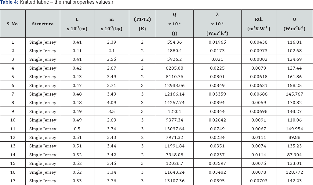
The instrument is first switched on. The temperature is then calibrated to the room temperature (29 °C) in both the chambers. The fabric is cut according to the template (5”x5”) and fixed over the glass plate, which is then inserted in the space between the two chambers. The test temperature T1 is then set using the setting knob. The changes in the temperature can be viewed on the LCD (Table 1-2). The heat is supplied by a horizontal air blower which blows in hot air generating the necessary amount of heat to be passed to the fabric through the glass plate. The glass plate is a good conductor of heat and thus helps conduct better transmission of heat through the fabric. These temperature changes are obtained by the temperature noting component called the Thermistor. There is a thermistor each in the two chambers which sense the temperatures and displays it on the LCD screen (Figure 1). The power is supplied and the temperatures are noted down until there are no changes in the temperature. Heat is passed through the fabric for at least one hour and the temperatures of T2 at the varying temperatures of T1 are noted down. The same procedure is repeated for various fabrics at various temperatures. Thus the difference in the temperature (T1-T2) is obtained from the instrument [10-14]. The following table gives various data's of the test samples for which the testing were carried out. All the samples are of the size 5"x5" (Table 3-4).


Formulae:
a. Heat Flow
b. Q= SHC x (T1-T2) x m
c. Thermal conductivity factor
d. λ = QL / At (T1-T2)
e. Heat transfer Coefficient
f. K= Q/At (T1-T2)
g. Thermal Transmittance
i. U = K/L
h. Thermal Resistance
a. Rth =L/K
Where,
SHC = Specific Heat Capacity of Cotton (1162 J/Kg C)
T1-T2= Temperature difference, in °C
m = Mass of the fabric, in Kg
L = Thickness of the fabric, in m
A= Area of the fabric used (0.016 m2)
t = Time of testing (3600s)


Results and Discussion
Woven fabric
With respect to thickness
The above is the graph (Figure 2) between thermal transmittance and fabric thickness of 100% cotton of woven fabric (plain weave). As the thickness (L) of the fabric increases, the thermal transmittance (U) value of the fabric decreases.

The above is the graph (Figure 3) between thermal resistance and fabric thickness of 100% cotton of woven fabric (plain weave). As the thickness (L) of the fabric increases, the thermal resistance (Rth) value of the fabric decreases.


The above is the graph between (Figure 4) thermal conductivity and fabric thickness of 100% cotton of woven fabric (plain weave). As the thickness (L) of the fabric increases, the thermal conductivity (X) value of the fabric increases [15].
With respect to mass
The above is the graph (Figure 5) between thermal conductivity and fabric mass of 100% cotton of woven fabric (plain weave). As the mass (m) of the fabric increases, the thermal conductivity (X) value of the fabric increases.

The above is the graph (Figure 6) between thermal conductivity and fabric mass (5”x5”) of 100% cotton of woven fabric (plain weave). As the mass (m) of the fabric increases, the thermal resistance (Rth) value of the fabric increases.

The above is the graph (Figure 7) between thermal transmittance and fabric mass (5”x5”) of 100% cotton of woven fabric (plain weave). As the mass (m) of the fabric increases, the thermal transmittance (U) value of the fabric decreases.
Knitted fabrics
With respect to thickness
The above is the graph (Figure 8) between thermal resistance and fabric thickness of 100% cotton of knitted fabric (single jersey). As the thickness of the fabric increases, the thermal resistance (Rth) value of the fabric increases [16].


The above is the graph (Figure 9) between thermal resistance and fabric thickness of 100% cotton of knitted fabric (single jersey). As the thickness of the fabric increases, the thermal resistance (Rth) value of the fabric increases. The unevenness is due to the variation in the cover factor [17-19].

The above is the graph (Figure 10) between thermal resistance and fabric thickness of 100% cotton of knitted fabric (single jersey). As the thickness of the fabric increases, the thermal Conductivity (X) value of the fabric increases .The unevenness is due to the variation in the cover factor
With respect to mass
The above is the graph (Figure 11) between thermal resistance and fabric Mass of 100% cotton of knitted fabric (single jersey). As the thickness of the fabric increases, the thermal Resistance Rth value of the fabric increases. The unevenness is due to the variation in the cover factor


The above is the graph (Figure 12) between thermal resistance and fabric Mass of 100% cotton of knitted fabric (single jersey). As the thickness of the fabric increases, the Thermal conductivity (X) value of the fabric increases .The 8. unevenness is due to the variation in the cover factor
The above is the graph (Figure 13) between thermal resistance and fabric Mass of 100% cotton of knitted fabric (single jersey). As the thickness of the fabric increases, the thermal Transmittance U value of the fabric increases .The unevenness is due to the variation in the cover factor [20-22].
Conclusion
The thermal properties such as thermal transmittance, thermal resistance and thermal conductivity of textile fabrics varies with respect to the factors like fiber type, fabric structure, type of the weave fabric thickness, cover factor, texture of the fiber, weight of the fabric. The factors observed for this project are fiber type, fabric structure, fabric thickness and weight of the fabric. As far as our instrument in concerned, from the observations, we can conclude that for the woven fabrics as the thickness increases, the thermal transmittance decreases and the thermal resistance increases, similarly as the mass of the fabric increases the thermal transmittance decreases and the thermal resistance increases. Also for the knitted fabrics, as the thickness increases, the thermal transmittance decreases and the thermal resistance increases, similarly as the mass of the fabric increases the thermal transmittance decreases and the thermal resistance increases. All the factors of the fabric are interrelated in determining the thermal properties of the fabric. One particular factor with relevance to the other only will give the final behavior of the fabric towards thermal exposure. Therefore the thermal transmittance value varies with respect to thickness, tightness factor and mass of fabric.
To know more about Journal of Fashion Technology-https://juniperpublishers.com/ctftte/index.php


Comments
Post a Comment